English
 中文简体
中文简体 русский
 عربى
عربىOuick Product Search
Provide Hengcai OEM program, product name and other information. The content of this information is for reference only.
2026-10-14
A dump truck does one job everyone recognizes: it tips its body and the load slides out of the tailgate. What happens between the driver pulling a lever and the bed rising is a compact hydraulic circuit that borrows engine power, meters oil through a valve, and lets pressure do the heavy lifting. Follow that chain in order and the system stops looking complicated, and a slow or sagging hoist becomes much easier to diagnose.
This guide follows the oil from the power take-off through the pump, reservoir, control valve, hoist cylinder and return line, and explains the details that decide lift speed, capacity and reliability.
Almost every tipper on the road uses the same components. The difference between a light truck and a quarry machine is size, pressure rating and mounting, not layout.
| Component | Function | Typical detail |
|---|---|---|
| Power take-off | Taps engine or transmission torque to drive the pump | Engaged from the cab by air or electric switch |
| Hydraulic pump | Converts mechanical power into oil flow | Normally a fixed-displacement gear pump |
| Reservoir and breather | Stores oil and lets trapped air escape | Suction strainer and breather are often neglected |
| Control valve | Directs oil to raise, hold or lower the body | Air or electric operation from the cab |
| Relief valve | Caps pressure and protects pump, hoses and seals | Set to the cylinder's rated pressure |
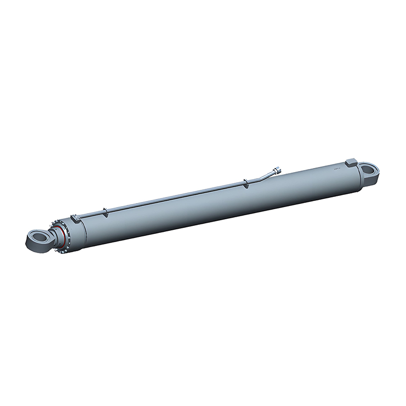
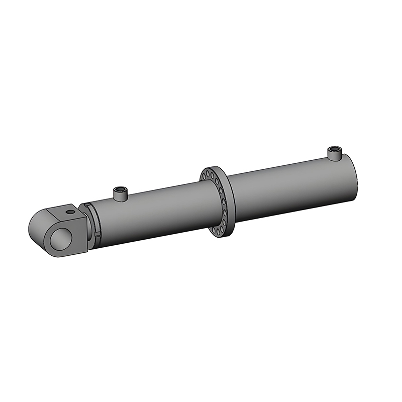
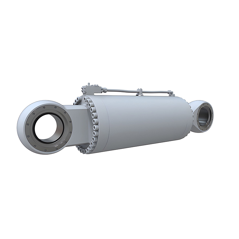
| Hoist cylinder | Converts oil pressure into lifting force | Usually single-acting and telescopic |
| Return line and filter | Returns oil to the tank and cleans it | A restriction here slows lowering |
The tipping system does not have its own engine. It borrows power through a power take-off, a gearbox that engages a driven gear against the transmission or an engine-driven pad. The driver normally engages it with the vehicle stopped, the park brake set and the transmission in neutral, so engagement is a deliberate safety step as much as a mechanical one. From that point the pump turns whenever the engine runs.
The pump is usually a fixed-displacement gear pump. It moves a set volume of oil for every revolution, so flow rises with engine speed. Flow is what sets lift speed: a larger pump, or more rpm, pushes oil into the cylinder faster. Pressure behaves differently. It only rises to whatever the load demands, and it stops at the relief valve setting. That is why a truck can idle a lift through when empty yet need more rpm under a full load, and why a truck that cannot lift at working rpm usually has a pressure problem rather than a flow problem.
Oil leaves the pump and enters the control valve, the decision point of the circuit. A cab lever, often connected by air or electric signal, moves a spool between raise, hold and lower.
In raise, pump flow is directed into the cylinder. In hold, the ports are blocked and trapped oil keeps the body at height. In lower, the spool opens the cylinder back to the reservoir. On a single-acting tipping cylinder nothing pushes the body down; gravity does the work, and the valve controls how quickly oil is allowed to escape. Many systems add a lowering restrictor or cushion so a heavy body does not drop with a bang.
The relief valve is the reason a stalled lift does not become a burst hose. When pressure reaches the set point, oil is dumped to tank. Set it too low and the truck will never lift a full load; set it too high and hoses, seals and cylinder walls see pressures they were never designed for.
Inside the cylinder, pressure acts on the area of the piston, and force equals pressure multiplied by area. A moderate pressure acting on a large area can raise several tonnes, which is why the hardware looks small next to the load it lifts.
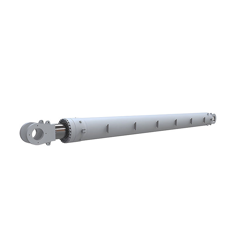
Most heavy tippers use a single-acting telescopic cylinder mounted at the front of the body or underneath it. Several sleeves nest inside one another, so the cylinder is short when retracted and long enough when extended to reach a full tipping angle. The largest diameter stage extends first. That is deliberate: when the body is level, the load has the greatest leverage against the cylinder, so maximum area, and therefore maximum force, is needed at the very start of the lift. As the body rises, smaller stages take over, and although their area is smaller, the geometry is now working in their favour.
Lowering reverses the sequence. The valve opens the path to tank, the weight of the body pushes the stages back in, and oil flows through the return line and filter into the reservoir. Double-acting cylinders are used where a body must be pulled down or held firmly, but on conventional tippers the return stroke is powered by gravity.
The mounting arrangement matters as much as the cylinder type. Choose the wrong layout and the body never reaches a clean tipping angle.
Whichever arrangement is chosen, the telescopic hydraulic cylinders and pump have to be matched to body length, payload and axle limits, not simply to the largest unit that fits.
 Logistics Equipment Hydraulic Cylinders for Material HandlingExplore actuators for forklifts, lifting platforms, stackers, conveyors, and sorting equipment, including tailboard and forklift cylinder types for precise lifting and telescoping.View Product →
Five variables explain most of the performance difference between one truck and another.
Stability is a separate issue from power. Raising a body moves the centre of gravity rearward, and a system that can lift a load cannot necessarily keep a truck upright on soft ground or a side slope. Operators should level the truck and watch the load, not just the pressure gauge.
Most tipping problems start with oil condition or seals rather than with the cylinder structure. Dirt, water and heat attack the same components. Contamination scores dump truck hoist cylinders and wears the pump; water from condensation causes corrosion during idle periods; sustained overheating thins the oil and accelerates seal wear and internal leakage.
Wiper seals on each exposed stage scrape dust and grit away from the sealing surfaces, which is why a torn wiper should be replaced early rather than left until the next service. Chrome-plated piston rods and honed tubes, clean hydraulic fluid and a filter changed on schedule do more for reliability than any single upgrade. Internal leakage past the piston seal is the usual reason a body creeps down or lifts slowly while the pump still sounds healthy.
A few patterns cover most field complaints on tipping systems.
When a hoist cylinder is replaced or a new body is specified, the measurements that matter are retracted and extended length, stage count, stage diameters, port size and thread, mounting pin diameter and the relief setting of the circuit. A cylinder that matches the mounting but not the pump flow will be either slow or over-pressured.
It also helps to work with a manufacturer that produces the whole assembly rather than only the outer sleeve. Jiangsu Hengcai Hydraulic Mechanical Co., Ltd. has been building hydraulic cylinders since 1988, supplying single-acting and double-acting units, welded and tie-rod designs, seal kits, cylinder barrels, honed tubes and chrome-plated piston rods, including interchangeable and ISO, metric and imperial standard ranges for both new equipment and replacement work.
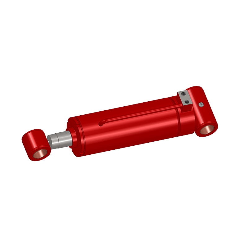 Construction Hydraulic Cylinders for Engineering MachineryExplore excavator, loader, crane, pump truck, and aerial work cylinders from a manufacturer producing complete hydraulic assemblies for construction machinery.View Product →
Whatever the truck hauls, the principle stays the same: engine-driven flow, controlled by a valve, converted into force by a cylinder with enough area to do the job, day after day.
Recommended Products

Copyright © Jiangsu Hengcai Hydraulic Mechanical Co., Ltd. All Rights Reserved.
 Custom Hydraulic Cylinders Manufacturers