English
 中文简体
 русский
 عربى
Ouick Product Search
Provide Hengcai OEM program, product name and other information. The content of this information is for reference only.
2026-10-29
When engineers search for how to design a cylinder, they quickly find that the topic goes far beyond drawing a simple geometric shape. A hydraulic cylinder is a precision assembly that converts fluid pressure into controlled linear force. Every design decision, from bore diameter to seal groove depth and surface finish, affects reliability, efficiency, and service life. This guide walks through the practical engineering steps so you can design a cylinder that performs well in real operating conditions, not just on paper.
Before any calculations begin, gather the full set of operating conditions. The parameters below directly shape the design:
Duty cycle matters as much as peak load. A cylinder that cycles continuously at high pressure needs different seals, cooling, and bearing design than one that operates occasionally under moderate load. Collecting these data first prevents the common mistake of designing around a single maximum force value and then discovering that fatigue, heat, or contamination limits real service life.
The next step is choosing the architecture. Single-acting cylinders use pressure for extension and rely on gravity or an external load for retraction, so they are simple and cost-effective for push-only applications. Double-acting cylinders apply pressure in both directions, giving the machine full control over advance and return. Telescopic cylinders collapse into a short package and extend through multiple stages, which is ideal for dump bodies and other space-constrained equipment.
Construction philosophy also matters. Tie-rod cylinders are assembled with threaded rods and are easy to service, making them popular in industrial environments. Welded-bodied cylinders use a welded barrel and end caps, offering a more compact and rugged design for mobile and heavy-duty equipment. The table below compares these families.
| Configuration | Typical Applications | Primary Advantage |
|---|---|---|
| Single-acting | Lifting platforms, clamping devices | Simple circuit, lower cost |
| Double-acting | Excavators, cranes, presses | Powered motion in both directions |
| Telescopic | Dump trucks, vehicle tailboards | Long stroke from short retracted length |
| Tie-rod | Industrial equipment, machine tools | Serviceable and rebuildable |
| Welded-bodied | Mobile equipment, mining, marine | Compact, rugged, high load capacity |
For underground mining and longwall support systems, welded-bodied cylinders with heavy-duty bearings and impact-resistant seals are the norm. The configuration decision determines how the rest of the design, from bore sizing to mounting, will be approached.
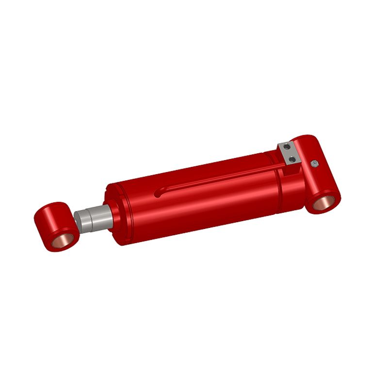
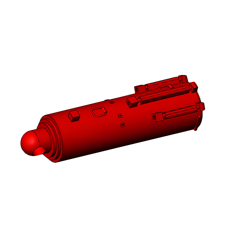 Hydraulic Support Cylinder for Longwall Mining SystemsThis cylinder is central to coal mine roof supports, offering lifting, locking, and load-bearing functions. Its bore and stroke are selected based on required forces and system pressure, matching the design approach described.View Product →
Once the configuration is fixed, the main dimensions follow from the required forces and speed. The bore diameter is determined by the push force and the available system pressure:
Bore area = Push force / Working pressure
For double-acting cylinders, the retraction force is calculated using the annular area between the bore and the rod. Rod diameter is then selected to handle both tensile and compressive loads. On the compression side, the rod behaves as a column, and long strokes can lead to buckling. The Euler buckling formula provides a useful check: the critical load depends on rod diameter, unsupported length, and the end conditions created by the mounting style.
Stroke length comes from the machine's motion range, but two additional checks are important. Verify that the piston has enough bearing length to resist side loads without metal-to-metal contact. Also check that the rod does not whip or vibrate when fully extended at speed. An excavator arm, for example, subjects its boom cylinder to high dynamic loads and repeated reversals, so the rod must be sized conservatively from the start.
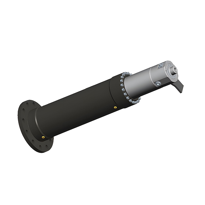
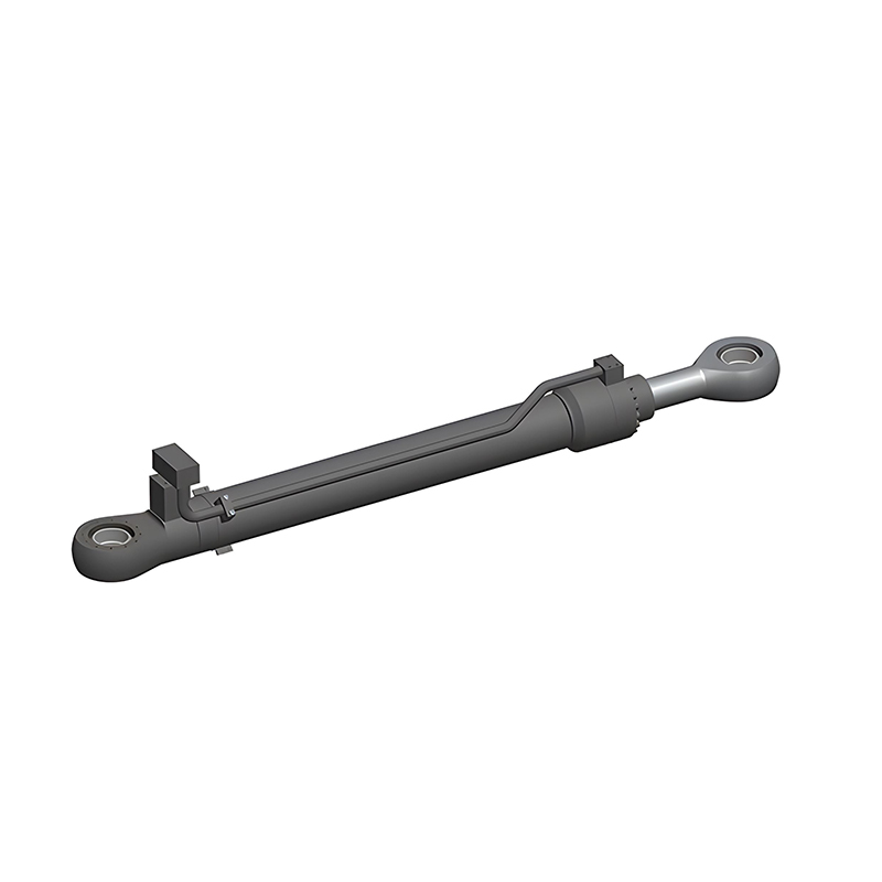 Excavator Hydraulic Cylinder with Robust Rod and Corrosion ResistanceBuilt for excavators from 1.5 to 700 tons, this cylinder handles boom, arm, and bucket duties. The hard chrome rod and TSZ coating suit the high dynamic loads and repeated reversals typical of excavator applications.View Product →
The barrel is commonly manufactured from cold-drawn seamless steel tubing, honed to a precise inside diameter and superfinished to reduce seal wear. End caps and flanges are typically forged or machined from carbon steel, with strength matched to the pressure rating. For corrosive environments, stainless steel barrels and end caps avoid the pitting and plating failures that carbon steel can suffer.
The piston rod is one of the most visible wear components. Hard chrome-plated piston rods offer a low-friction surface that resists scoring and corrosion. The hard chrome layer is typically ground and polished to a fine finish so the rod seal glides smoothly and keeps contamination out. In agricultural machinery, cylinders work outdoors in dusty and muddy fields, so the rod finish and wiper selection are critical to long-term reliability.
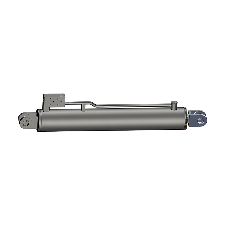
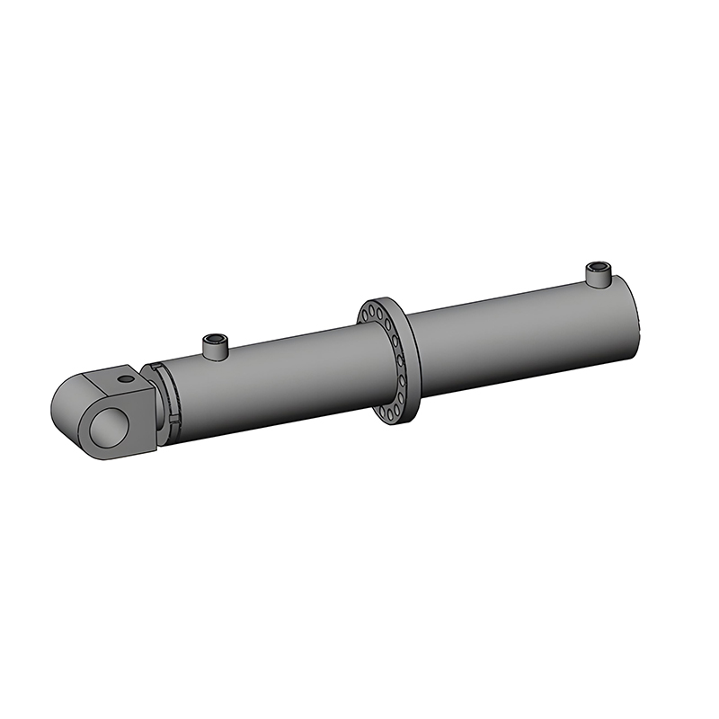 Agricultural Machinery Hydraulic Cylinder with Durable SealingDesigned for dusty, muddy field conditions, this cylinder uses compound sealing and corrosion-resistant materials. It supports lifting, depth adjustment, and folding functions on implements, with options for integrated valves to save space.View Product →
The sealing system is the heart of a reliable cylinder. Rod seals keep pressure fluid inside while preventing contamination from entering along the rod surface. Piston seals separate the two pressure chambers, and wipers scrape dirt and moisture off the rod before it re-enters the cylinder.
Seal material depends on fluid compatibility, temperature range, pressure, and speed. Nitrile rubber suits mineral oils at moderate temperatures, while polyurethane is durable in abrasive environments. PTFE seals handle higher speeds and wider temperature ranges. Groove dimensions, tolerances, and surface finish are specified by the seal manufacturer, and following them closely is essential. A smooth rod surface and a clean bore extend seal life by a wide margin.
Mounting style transfers the cylinder's force into the machine structure. Clevis and trunnion mounts allow angular movement, flanges provide rigid support, and foot mounts are simple and compact. The mounting arrangement changes the effective length used in buckling calculations, so it should be defined before the rod diameter is finalized.
Port types, sizes, and locations must match the system's flow requirements. Large ports minimize pressure drop at high flow. Position the ports so air can be bled easily during installation. For high-speed motion, end-of-stroke cushions may be required to decelerate the load smoothly and prevent impact damage.
Even a well-calculated design benefits from a physical prototype. Machining a prototype cylinder lets you confirm dimensional fit, assembly effort, seal compression, and overall function before volume production. The prototype also provides a sample for mounting mock-ups and cycle testing on the actual machine.
Testing should go beyond a static pressure check. A typical development program moves through several verification steps:
When a design passes these tests, it is ready for production. Partnering with a manufacturer that offers hydraulic cylinder prototyping services shortens the development cycle and gives you direct feedback on manufacturability.
Designing a cylinder for hydraulic power is a systematic process. Start with the operating envelope, choose a configuration that fits the machine, calculate bore and rod dimensions with force and buckling in mind, select materials that match the environment, and pay close attention to the sealing system and mounting. Then verify everything through prototyping and testing.
With a clear methodology, you can design a cylinder that is reliable, efficient, and well matched to the equipment it serves.

Copyright © Jiangsu Hengcai Hydraulic Mechanical Co., Ltd. All Rights Reserved.
 Custom Hydraulic Cylinders Manufacturers