English
 中文简体
 русский
 عربى
Ouick Product Search
Provide Hengcai OEM program, product name and other information. The content of this information is for reference only.
2026-10-27
Dimensioning a hydraulic cylinder is more than picking a few round numbers from a catalogue. It means defining the geometry that determines how much force the actuator can push and pull, how far it travels, how it connects to the machine, and whether it fits the space you have. Get the dimensions right, and the cylinder installs cleanly and cycles reliably for years. Get them wrong, and you are likely to discover the problem only after the machine is already apart.
Before you measure or calculate anything, define the job. System working pressure, required push and pull forces, stroke, cycle speed, ambient temperature, and environmental exposure all feed into the dimensioning process. A cylinder that works well in a clean indoor press will not survive on a coastal crane, and one that is perfect for an agricultural attachment may not handle the shock loads of an excavator.
Write those operating conditions down before you open the calipers. They form the design inputs that every dimension will have to answer to: what pressure is available, which direction the force must work, how long the stroke needs to be, what space exists in the retracted and extended positions, and how the cylinder should be mounted. Keep that list beside you while you work through the bore, rod, and stroke.
The bore, or inner diameter of the barrel, is the dimension that controls pushing force. Pressure acts on the piston area, so the larger the bore, the more force you get at the same system pressure. The relationship is straightforward: F = P × A, where F is force, P is working pressure, and A is the effective piston area. Since A = π × (bore/2)², even a small increase in bore produces a noticeable gain in force. Bore size also drives oil flow demand, because a larger bore needs more oil to fill on every stroke. Barrel wall thickness must be matched to working pressure as part of the same decision, which is why selecting a hydraulic cylinder barrel goes hand in hand with choosing the bore. On an excavator, for example, boom and stick cylinders are dimensioned around peak breakout force at high pressure and heavy side loads.
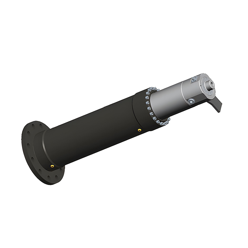
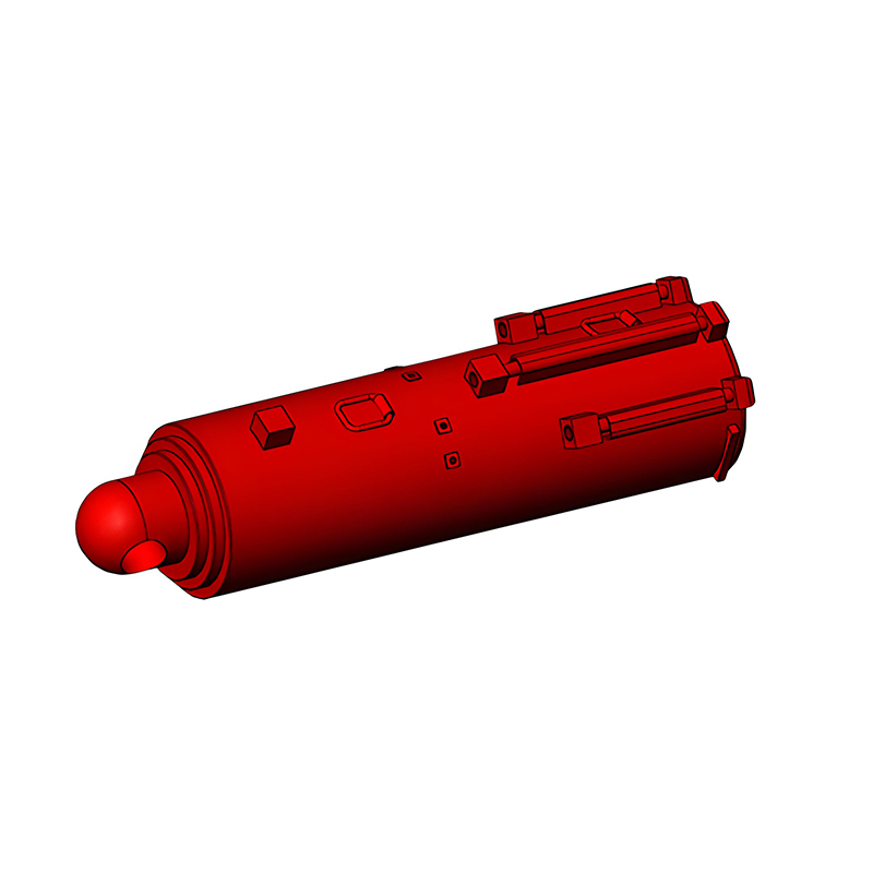
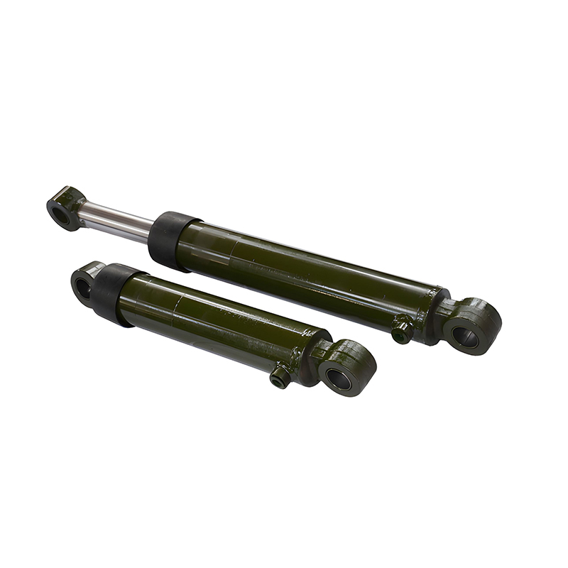
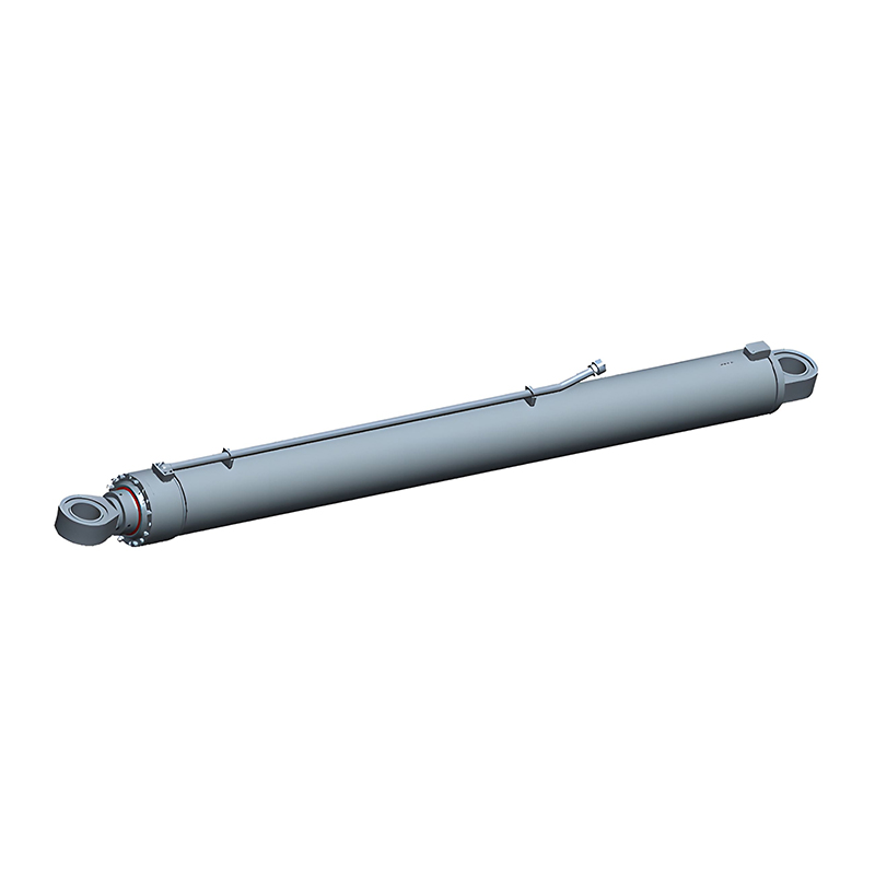
 Excavator Hydraulic Cylinder for Heavy-Duty ApplicationsBore size directly determines pushing force. This excavator cylinder offers bores up to 420 mm and push force to 4800 kN, matching the force-calculation principles discussed here.View Product →
The rod carries the force to the load, and in most installations it works in compression when pushing. Long-stroke cylinders with slender rods risk buckling under load, so rod diameter is often set by mechanical stability as much as by pull force. In retract, the rod takes up part of the piston area, which means pulling force is always lower than pushing force at the same pressure. To find pull force, subtract the rod area from the piston area before multiplying by pressure. If the rod is undersized for the stroke, the cylinder may vibrate, bow, or wear the seals prematurely. That is why most heavy-duty cylinders rely on chrome-plated piston rods that resist surface damage and keep the sealing surface smooth.
Stroke is the travel distance between the fully retracted and fully extended positions. It is not an overall length. The retracted and extended lengths combine stroke with the lengths of the base mounting, the piston assembly, and the rod end, so two cylinders with the same stroke can have completely different installed lengths. When dimensioning a cylinder, always confirm that the extended length clears the machine frame at the outermost point of the cycle. Forklift mast cylinders show the trade-off clearly: they need a long, precise stroke in a compact envelope, so retracted length is just as important as travel.
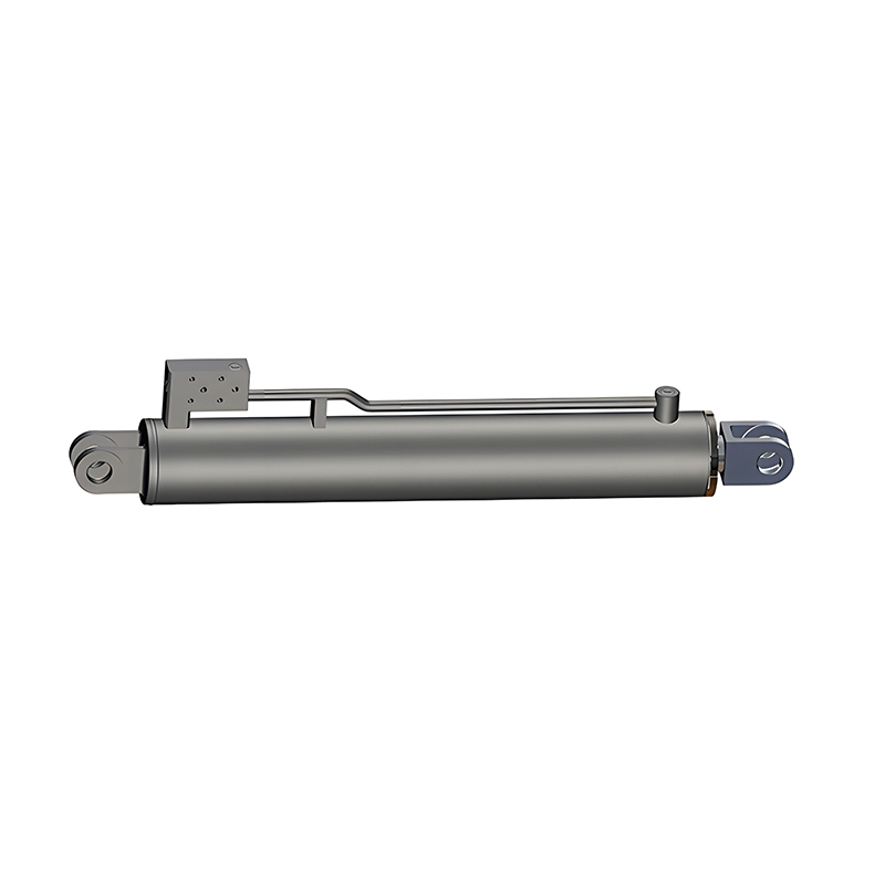
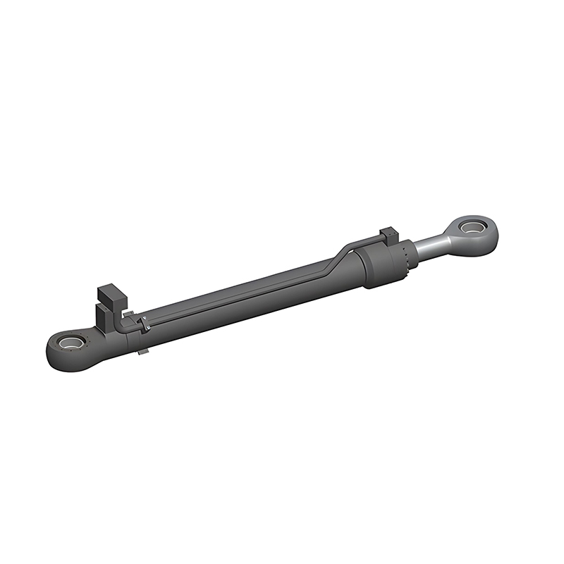
 Forklift Hydraulic Cylinder with Precise Stroke ControlStroke and installed lengths are critical for forklift masts. This cylinder supports strokes up to 3000 mm with long-stroke support technology, fitting the envelope considerations mentioned above.View Product →
These two figures define the physical space the cylinder occupies. On an existing cylinder, measure from the centerline of the base pin to the centerline of the rod-end pin, or from the mounting face to the rod face, depending on the design. Record both numbers even if someone has already given you the stroke. The difference between extended and retracted length should equal the stroke; when it does not, you are probably looking at a cylinder that was rebuilt, modified, or misidentified.
With bore, rod, and stroke selected, the rest of the system math falls into place. Push force equals P × piston area. Pull force equals P × (piston area - rod area). Oil volume per stroke equals piston area × stroke in the extend direction and (piston area - rod area) × stroke in retract. Cycle time then sets the flow rate: Q = V/t.
These numbers explain why oversizing a cylinder is not a harmless safety margin. A larger bore consumes more oil on every cycle, which demands a larger pump, a larger reservoir, and more hydraulic power to do the same work. Undersizing is worse: the system either cannot reach the required force, or pressure must be pushed beyond the design limits of the seals and hoses. Dimensioning is a balance rather than a one-way street.
The table below shows theoretical push force for common metric bores at two working pressures. Real values are lower once seal friction and system pressure losses are included, but the relative comparison remains valid.
| Bore (mm) | Piston Area (cm²) | Force at 16 MPa (kN) | Force at 25 MPa (kN) |
|---|---|---|---|
| 40 | 12.6 | 20.1 | 31.4 |
| 50 | 19.6 | 31.4 | 49.1 |
| 63 | 31.2 | 49.9 | 77.9 |
| 80 | 50.3 | 80.4 | 125.7 |
| 100 | 78.5 | 125.7 | 196.3 |
A hydraulic press, by contrast, is dimensioned for sustained force rather than rapid cycling, so the bore is sized with reserve at the continuous working pressure.
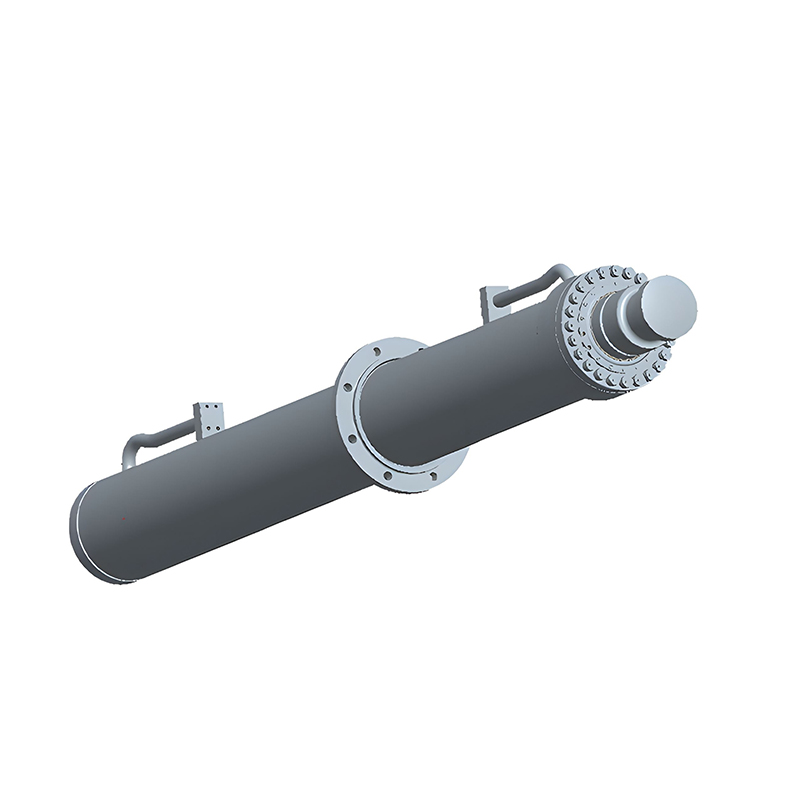
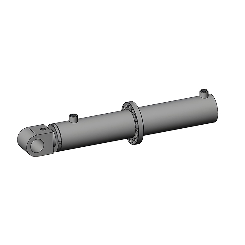
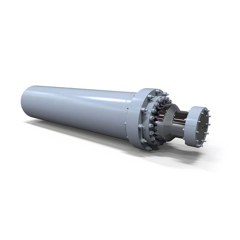 Hydraulic Press Cylinder for High-Force Sustained OperationsHydraulic press cylinders need continuous force capability. This model reaches 8500 kN push force with robust guides, suitable for the sustained-load requirements described.View Product →
The mounting style decides how the cylinder reacts against the machine frame, and it directly affects the envelope. Common mounting families include:
Each style changes the reference points you use for retracted and extended length, so those dimensions shift from pin centers to flange faces to trunnion centers. The end caps and clevises used on the cylinder determine which of these mounting options the unit can support.
Rod end attachments, whether a clevis, an eye, a spherical bearing, or a threaded stud, occupy different spaces and take different loads. Record the rod end type and its dimensions, including pin bore and thread size, so the replacement matches the original linkage.
Ports are the dimension set that gets forgotten most often. Size, thread type, and location all matter. A cylinder that fits perfectly but has ports facing the machine frame may be impossible to connect. Note whether the ports are in the head, the base, or the barrel, and record the thread standard (SAE, JIC, BSPP, or metric) so the existing hoses can be reused without adapters.
After decades of building hydraulic cylinders for excavators, cranes, presses, and marine equipment, we have seen where the dimensioning process tends to go wrong. The table below lists the most frequent issues we encounter when customers send us their measurements.
| Mistake | Why It Happens | How to Avoid It |
|---|---|---|
| Confusing stroke with extended length | Stroke is travel, extended length is overall | Record retracted and extended lengths as well as stroke |
| Guessing bore from barrel outside diameter | Wall thickness adds to the bore | Measure the piston or barrel inner diameter directly |
| Forgetting that pull force is lower than push force | Rod area reduces effective piston area | Calculate pull force before fixing the rod diameter |
| Omitting port orientation | Envelope fits, but hoses cannot connect | Note thread type, size, and port position on the sketch |
| Ignoring buckling on long strokes | Slender rod under compression is unstable | Check rod diameter against stroke and side-load conditions |
For a broader view of the selection procedure, including pressure ratings and duty-cycle considerations, see our step-by-step guide on how to size a hydraulic cylinder.
Once your dimensions are recorded, a competent manufacturer will compare them against existing standard designs before suggesting a custom build. Many cylinders that look special turn out to match a standard product with a different rod end, a relocated port, or a modified clevis. That kind of comparison saves money and lead time, which is why it helps to work with a factory that machines its own barrels, piston rods, end caps, and clevises rather than simply assembling sourced parts.
This is also where experience surfaces. A manufacturer who has supplied cylinders for construction machines, presses, forklifts, marine cranes, and mining equipment can look at a bore and stroke combination and immediately see whether the rod is likely to buckle, whether the mounting will suffer side loads, and whether the sealing arrangement suits the environment. Dimensioning is the language; application experience is what makes it useful.

Copyright © Jiangsu Hengcai Hydraulic Mechanical Co., Ltd. All Rights Reserved.
 Custom Hydraulic Cylinders Manufacturers