English
 中文简体
 русский
 عربى
Ouick Product Search
Provide Hengcai OEM program, product name and other information. The content of this information is for reference only.
2026-11-12
A hydraulic power unit is often called the heart of a hydraulic system, but it is easier to understand as a packaged energy converter. It takes electrical or engine power, drives a pump, and delivers fluid at controlled pressure and flow. That fluid then moves an actuator, such as a hydraulic cylinder, which turns hydraulic energy into linear force. If you are asking how a hydraulic power unit works, the short answer is: it stores, pressurizes, cleans, controls, and routes fluid to where the machine needs it.
At Jiangsu Hengcai Hydraulic Mechanical Co., Ltd., we have focused on hydraulic cylinders since 1988. Our experience with construction, mining, marine, agricultural, and industrial equipment gives us a practical view of what a power unit must do to keep the whole circuit productive.
A power unit does not create force directly. It creates flow. The pump draws fluid from the reservoir and pushes it into the pressure line. Resistance from a cylinder, motor, or valve creates pressure, and pressure acting on an actuator area produces force. In a cylinder, pressure on the piston area produces thrust; flow determines how fast the piston moves. That relationship explains most power unit behavior.
Most HPUs follow the same energy path: prime mover, pump, pressure and directional controls, actuator, and return line. The prime mover may be an electric motor in a stationary unit or a diesel engine on mobile equipment. The pump may be fixed displacement, delivering the same volume per revolution, or variable displacement, adjusting output to demand. The reservoir holds fluid, lets air separate, and helps dissipate heat. Filters remove particles, and a cooler removes heat produced by pressure drops.
Although layouts vary, most hydraulic power units combine the same functional groups. The table below shows what each part contributes.
| Component | Main job | What to watch |
|---|---|---|
| Reservoir | Stores fluid, separates air, and supports heat dissipation | Oil level, baffles, breather condition, and contamination |
| Pump | Converts mechanical power into hydraulic flow | Displacement, pressure rating, speed, and inlet conditions |
| Electric motor or engine | Drives the pump at the required speed and torque | Power match, starting load, and duty cycle |
| Pressure controls | Limit pressure and protect the system from overload | Relief valve setting, response, and valve stability |
| Directional and flow valves | Send fluid to the right actuator at the right speed | Center condition, leakage, pressure drop, and control method |
| Filters and cooler | Keep fluid clean and within a safe temperature range | Filter rating, bypass condition, cooler airflow, and oil temperature |
The reservoir is not just a tank. It gives returning fluid time to slow down, release air, and shed heat. Baffles separate suction from return flow, and the breather, sight glass, and drain points matter for service. The pump creates flow, not pressure; pressure rises only when flow meets resistance. A fixed pump is simple but may send excess flow over the relief valve, wasting energy and creating heat. A variable pump can reduce output as demand falls. Relief valves limit maximum pressure, directional valves route flow, and flow controls set actuator speed. Return filters and pressure filters protect sensitive parts, while gauges and sensors make the unit monitorable.
When the valve returns to neutral, flow may be blocked, bypassed, or unloaded. In a closed-center circuit, the pump may destroke or unload; in an open-center circuit, flow circulates at low pressure. The choice affects energy use, heat, and response.
Open-center and closed-center describe what happens to pump flow in neutral. An open-center valve lets flow pass through the center path back to the reservoir, which is common in simpler systems but can waste energy if the pump keeps delivering full flow. A closed-center valve blocks the center path, so the pump must destroke, unload, or otherwise limit pressure. Closed-center systems can be more efficient, but they need careful control design.
Pump control matters just as much. A fixed pump with a relief valve is straightforward but continuous relief flow creates heat. A pressure-compensated variable pump adjusts displacement to hold a set pressure, and a load-sensing pump adjusts flow to match actuator demand. The right choice depends on the duty cycle, simultaneous functions, and how much energy loss the machine can tolerate.
Sizing starts with the actuator, not the pump. For each cylinder, determine required force, bore, rod diameter, stroke, and cycle time. Force comes from pressure and piston area; speed comes from flow and piston area. If a cylinder must extend in two seconds, calculate the required flow from swept volume and time, then add simultaneous functions, leakage, and efficiency losses.
Next, check pressure. The relief valve setting must be above the highest working pressure but within the rating of the pump, valves, seals, and cylinders. For heavy industrial hydraulic supply, this usually means starting with the duty cycle, not just the maximum load. A machine that holds pressure for long periods may need different pump control than one that moves rapidly through short cycles. Reservoir volume, cooler capacity, and filter flow rating should be sized for heat load, not guessed from pump flow alone.
Most power unit problems show up as heat, noise, slow movement, or leakage. Start with fluid level, filter indicator, breather condition, pump inlet restrictions, and cooler airflow. A noisy pump may be cavitating because the suction line is restricted or the fluid is too cold. Dark or burnt-smelling fluid may have overheated. A filter in bypass is no longer protecting the system.
Air ingress is another common issue. Air can enter through a loose suction fitting, low reservoir level, or worn rod seal. In a cylinder, air causes spongy movement and inconsistent speed. Seal wear is normal, but repeated failure may point to contamination, misalignment, or side load. Keeping spare hydraulic cylinder seal kits on hand can shorten downtime, but the root cause should still be corrected. Check oil temperature regularly; hot oil thins, leaks more, and ages seals faster.
Power units appear in many shapes because machines have different priorities. Construction equipment needs fast response and rough-duty reliability. Mining equipment needs high force and contamination protection. Marine equipment needs corrosion resistance in wet, salty conditions. Agricultural equipment needs efficient operation across varying temperatures and loads. Waste and recycling equipment needs stable force under repeated cycling.
For marine and offshore equipment, the power unit and cylinder must be selected as a system. A marine crane cylinder may face salt spray, deck motion, and long holding periods, so rod material, coating, seals, and mounting details matter as much as bore and stroke.
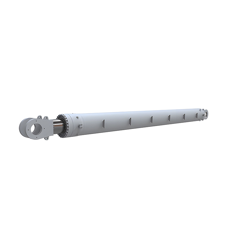 Marine Crane Hydraulic Cylinder for Shipboard and Offshore CranesFor marine and offshore equipment, this cylinder pairs corrosion-resistant rod coating, marine-grade seals, and customizable mounting with crane-specific sizing.View Product →
In construction, excavator cylinders must handle shock loads, side forces, and pressure spikes. The power unit may use a load-sensing pump and a valve block that prioritizes functions. The cylinder design affects force, stability, service life, and operator feel.
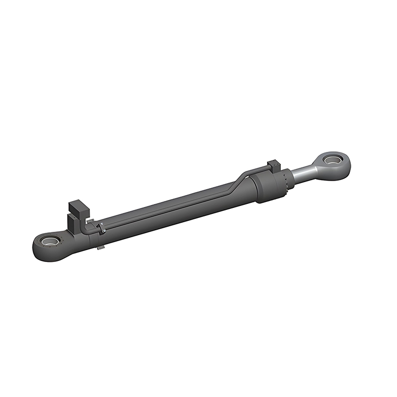 Excavator Hydraulic Cylinders for Boom, Arm, and Bucket CircuitsFor 1.5 t to 700 t excavators, this cylinder offers standardized design, tuned cushioning, and customizable mounting for boom, arm, bucket, and attachment circuits.View Product →
Agricultural machinery often runs in dusty, variable conditions. A cylinder that is easy to rebuild and well protected at the rod seal can keep a machine in the field rather than in the shop.
The power unit sets flow and pressure; the cylinder converts them into force and motion. If the bore is too small, the system may need higher pressure than the pump or valves can deliver. If the rod is too large relative to the bore, retract force and speed may be limited. If the stroke is long, the oil volume may require a larger pump or accumulator. These are not isolated details; they are one circuit.
At Hengcai, our work since 1988 has centered on hydraulic cylinders for OEM and replacement applications. We support custom development from drawings or samples, and we understand that a cylinder is only as good as the system around it. Share working pressure, flow, cycle time, mounting arrangement, and environment at the start of a project, not after the cylinder is built.
Understanding how a hydraulic power unit works comes down to a simple idea: the unit prepares and controls flow, and the actuator turns that flow into useful work. When reservoir, pump, valves, filters, cooler, and cylinder are matched to the real duty cycle, the system runs cooler, responds better, and lasts longer. When one part is chosen in isolation, the whole circuit pays the price.

Copyright © Jiangsu Hengcai Hydraulic Mechanical Co., Ltd. All Rights Reserved.
 Custom Hydraulic Cylinders Manufacturers