English
 中文简体
 русский
 عربى
Ouick Product Search
Provide Hengcai OEM program, product name and other information. The content of this information is for reference only.
2026-11-09
Ask anyone on our shop floor what makes a hydraulic system move, and most people will point at the cylinder. That is fair, because the cylinder is where the visible work happens. But a cylinder is only a receiver. Something has to push the oil into it, and on a huge number of machines, from tractor loaders to small presses, that something is a gear pump. We have been building hydraulic cylinders since 1988, and we have spent just as long listening to customers describe the pumps sitting upstream of them. Here is how a gear pump works, in plain language.
A gear pump is a positive displacement pump. Two meshing gears trap a fixed volume of oil in the spaces between their teeth and the casing, carry that oil around the inside of the housing, and squeeze it out the delivery side. Because the volume moved per revolution is essentially fixed, flow depends on speed rather than on pressure. That one fact explains most of the pump's strengths and nearly all of its limitations.
Strip a gear pump down and you find a surprisingly short list of parts. The simplicity is the reason these pumps survive decades of abuse in dirty, hot, vibrating machinery.
Follow one pocket of oil through a single revolution and the whole cycle becomes easy to picture.
Most industrial and mobile gear pumps are external, meaning both gears sit side by side and mesh at a single point between them. Internal gear pumps place a smaller gear inside a larger ring gear, with a crescent-shaped filler separating the two. The internal layout is quieter and handles thick fluids more gracefully, while the external layout is cheaper, easier to service and available almost anywhere.
| Characteristic | External gear pump | Internal gear pump |
|---|---|---|
| Typical pressure range | Up to about 250 bar continuous | Up to about 300 bar in premium designs |
| Noise level | Moderate to noticeable | Noticeably quieter |
| Viscosity tolerance | Good across a wide band | Excellent with thick oils |
| Service and cost | Simple, low cost, widely stocked | Higher cost, tighter tolerances |
| Common duty | Mobile hydraulics, power packs, charge pumps | Presses, industrial circuits, quiet installations |
In both cases the working principle is identical: trap, carry, squeeze. Only the geometry changes.
Every pump has a displacement figure, the volume it moves per revolution. Flow is roughly displacement multiplied by shaft speed, adjusted for losses. A pump rated at 20 cubic centimetres per revolution turning at 1,500 rpm moves about 30 litres per minute in theory, and a little less in practice.
The gap between theory and reality is called slip: pressurised oil squeezes back past the tooth tips, the gear faces and the bearings. Slip grows with pressure, with wear and with hot, thin oil. That is why a tired pump still turns quietly but delivers noticeably less flow, and why a cold start with heavy oil can briefly raise pressure far above normal working levels.
On construction equipment, a gear pump driven from the engine feeds control valves that sequence boom, bucket and travel circuits on a machine such as an excavator.
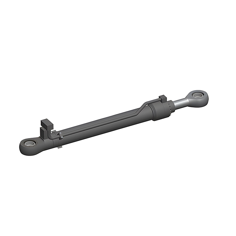 Excavator Hydraulic Cylinders for Boom, Arm and Bucket DutyDesigned for severe-duty excavator boom, arm and bucket circuits, with cushioning, sealing and customizable mounting for 1.5–700 t machines.View Product →
On a farm, the same principle runs loader arms, steering and hitch lift, often through a simple tandem pump stack feeding cylinders that work in dust and temperature swings all season.
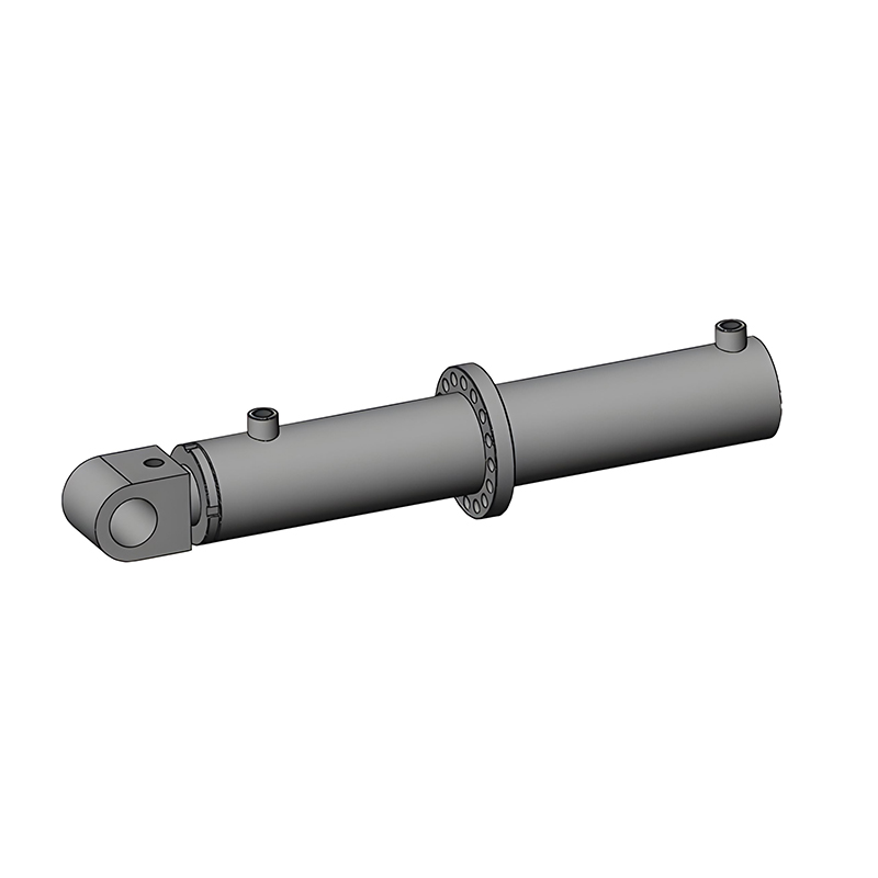 Agricultural Hydraulic Cylinders for Implements and Farm EquipmentBuilt for seed drills, tillers, balers and spray equipment, with compound sealing, integrated valve options and customizable OEM mounting.View Product →
Waste compaction is another classic duty: the pump builds pressure, the valve shifts, and the ram strokes smoothly through a heavy load before the relief valve takes over.
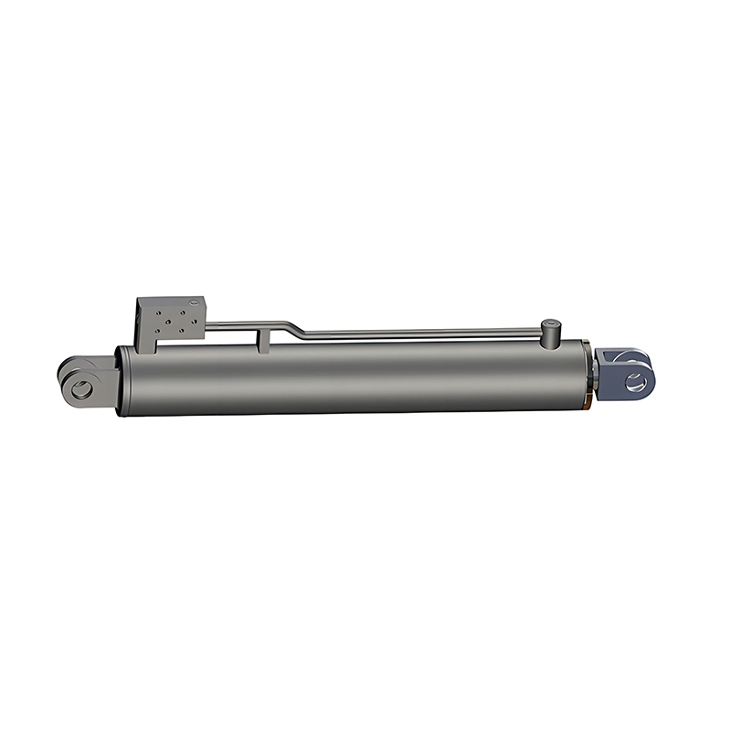 Garbage Compression Truck Hydraulic Cylinders for Refuse EquipmentDrives compaction, ejector and lift functions on 3–12 t refuse trucks, with floating buffers, sealing options and custom mounting configurations.View Product →
In most of these circuits the oil ends up in a double-acting hydraulic cylinder, which is exactly where the pump's steady delivery turns into force and motion.
A gear pump is tolerant, not indestructible. The usual failure routes are predictable.
Most of the gear pump problems we hear about start somewhere other than the pump. A few habits go a long way.
Wear usually shows up downstream as well, so inspect the rod and cylinder seal kits when you service the pump side of the circuit; oil that has been overheated or contaminated rarely leaves the cylinder untouched.
A gear pump is a fixed-displacement device, so circuit speed is normally controlled by valves or by engine speed. That matters when you specify the cylinder: bore and rod diameter decide how much force you get for a given pressure, while stroke and mounting decide how the pump's flow is used. Get the pairing right and a small pump will move a large load all day without complaint.
If you are sizing a cylinder for an existing gear pump circuit, or replacing a worn unit on equipment that has been in service for years, send us the working pressure, required force and mounting details. We have been matching cylinders to real machines since 1988, and we are always glad to talk through the numbers before anything goes into production.
Recommended Products

Copyright © Jiangsu Hengcai Hydraulic Mechanical Co., Ltd. All Rights Reserved.
 Custom Hydraulic Cylinders Manufacturers