English
 中文简体
 русский
 عربى
Ouick Product Search
Provide Hengcai OEM program, product name and other information. The content of this information is for reference only.
2026-11-16
A two-stage hydraulic pump is built around a simple observation: most hydraulic work does not need maximum flow and maximum pressure at the same moment. A cylinder often needs to travel quickly toward a load, then push slowly and forcefully through it. Trying to do both with one large pump wastes energy, heats oil, and demands a bigger motor. A two-stage pump splits the job between two pumping sections so the system can move fast at low pressure and then switch to a small, high-pressure stage.
The basic answer to how a two stage hydraulic pump works is this: both stages supply oil during the fast, low-pressure part of the cycle. When resistance rises, an unloading valve bypasses the large stage, and the small stage continues alone to build pressure. The cylinder slows down, but it gains force without asking the motor to produce the same high flow at high pressure.
Hydraulic power is flow times pressure. If a pump keeps delivering a large flow while pressure climbs, the power demand climbs with it. In a log splitter, press, or utility power pack, that would mean a larger motor, more heat, and a bulkier reservoir. The two-stage layout reduces power demand during the high-pressure phase by reducing flow.
The trade-off is speed. The high-pressure stage is smaller, so cylinder movement slows at changeover. That is acceptable in many duty cycles because the high-force portion is short. The fast approach does most of the travel, and the slow push does the actual work. If a machine needs continuous high pressure, a variable-displacement piston pump is often a better match.
Most two-stage pumps use two fixed-displacement pump sections, often gear sections, in one housing and driven by a common shaft. The large section provides high flow. The small section provides high pressure. The housing also contains check valves, an unloading valve, and usually an integral relief valve or a system relief elsewhere in the circuit.
The check valves keep oil from flowing backward into a stage that has been bypassed. The unloading valve controls the changeover. It senses pressure on the high-pressure side and, at its set point, opens a path from the large stage to the tank. Oil from the large stage then circulates at low pressure instead of fighting the load. The small stage keeps sending oil to the cylinder or motor.
Changeover is not a gear shift. It is a pressure-controlled diversion of flow. As the cylinder meets resistance, pressure rises. Once the unloading valve reaches its setting, the first-stage flow is dumped to tank and the second stage takes over. A check valve at the first-stage outlet closes, so high-pressure oil cannot back-drive the large section.
When the load falls, pressure drops, the unloading valve closes, and the first-stage flow rejoins the circuit. The exact changeover pressure is set by the valve spring, pilot pressure, or manufacturer calibration. It should not be treated as an adjustable performance knob without checking the whole system. Setting it too low makes the machine slow; setting it too high can overload the prime mover or force the relief valve to open unnecessarily.
The differences matter most when matching a pump to a cylinder and a duty cycle. The table below keeps the comparison practical.
| Pump type | Low-pressure flow | High-pressure flow | Typical strength | Typical limitation |
|---|---|---|---|---|
| Two-stage gear | High, with both stages combined | Low, from the small stage only | Fast approach plus short high-force push | Flow drops at changeover |
| Single-stage gear | Same as high-pressure flow | Same as low-pressure flow | Simple, low-cost circuit | Large motor or slow high-pressure work |
| Variable-displacement piston | Controlled by displacement | Controlled by displacement | Efficient continuous high pressure | Higher cost and cleanliness demand |
A one-stage gear pump is simpler, but it must carry full flow at high pressure or use a much larger motor. A piston pump can vary displacement and hold high pressure efficiently, but it costs more and usually requires tighter fluid cleanliness and control setup. A two-stage pump sits between them: compact and effective for fast-approach, short-push work.
You will see this layout in shop presses, log splitters, portable hydraulic power packs, and some tractor-mounted implements. The common thread is a repeated cycle with a long, lightly loaded approach and a short, heavily loaded working stroke. In a press, the ram can close quickly; in a splitter, the wedge can advance fast before the wood resists.
These pumps are less common as the main pump on excavators and other mobile machines that need precise, simultaneous control of several functions. Those machines usually rely on variable-displacement piston pumps and load-sensing systems. A two-stage gear pump is a good solution for a dedicated, single-function circuit, not a universal upgrade.
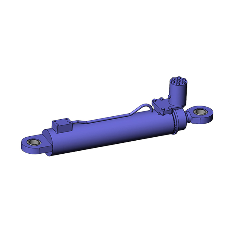
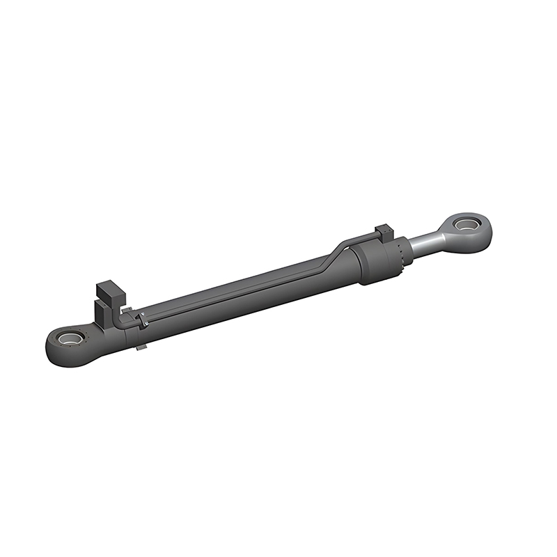
For press builders, our hydraulic press cylinder range is built around the bore, rod, and seal package that this kind of circuit demands.
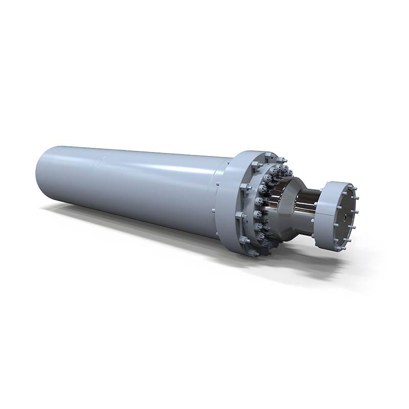 Hydraulic Press Cylinders for Press and Forming LinesBuilt around bore, rod and seal requirements for press circuits, with customizable mounting, stroke, cushioning and sensing options.View Product →
On the cylinder side, two simple relationships explain what the operator feels. Cylinder speed depends on flow divided by effective area, and force depends on pressure times effective area. When the pump switches to the small stage, flow drops, so the rod slows. Pressure rises because the load is now being moved with less flow and the relief valve has not opened.
A large-bore cylinder can produce a lot of force at modest pressure, but it needs more flow to move at a given speed. A small-bore cylinder moves faster for the same flow but needs higher pressure to do the same work. This is why a two-stage pump and a cylinder should be selected together rather than separately. The changeover point, cylinder area, stroke length, and relief setting form one performance package.
The same rules apply to double-acting hydraulic cylinders on the return stroke, though the rod-side area is smaller and the speed and force relationship changes. For a component-level explanation of bore, rod, seals, and pressure, see our hydraulic cylinder operation guide.
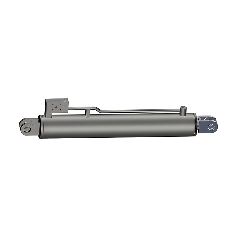
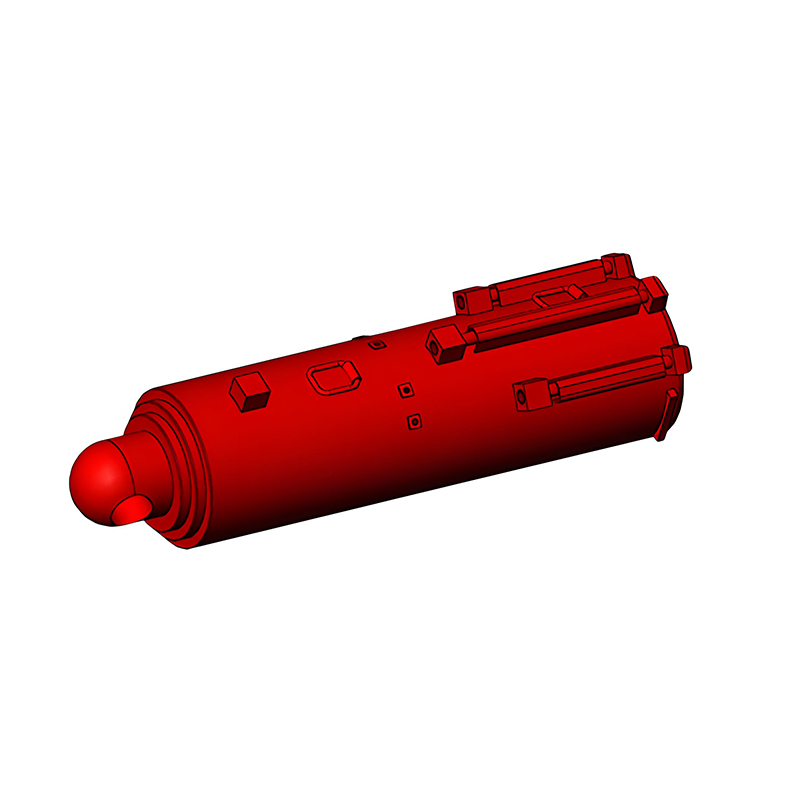
In agricultural equipment, the same fast-approach and hard-push logic appears in loader lift, implement tilt, and small press circuits. Our agricultural machinery cylinder line is built around those field-duty cycles, with sealing and rod choices matched to dust, weather, and regular use.
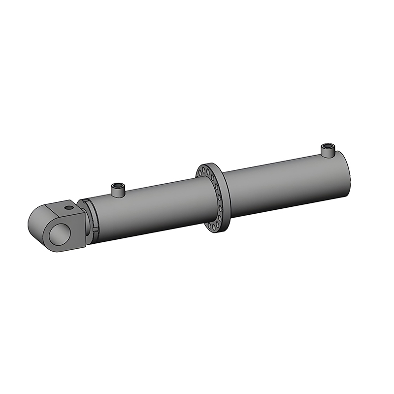 Agricultural Machinery Hydraulic Cylinders for Field DutySealing and rod choices suit dust, weather and regular use, with optional integrated valves for implement lift, tilt and positioning.View Product →
Start with the duty cycle, not the pump label. Note the force required, the stroke, the time allowed for approach and press, and the pressure limit of the cylinder and hoses. Then calculate flow from cylinder area and speed. The pump's high-pressure stage must supply enough flow for the working stroke, and the low-pressure combination must supply enough for the approach.
A two-stage hydraulic pump works by matching flow to the easy part of the cycle and pressure to the hard part. Both stages feed the circuit at low pressure; at changeover, the large stage is unloaded and the small stage builds pressure. That is why the cylinder can approach quickly and then push with controlled force using a smaller prime mover.
When the pump, cylinder, and relief settings are selected as a system, the result is a simple, efficient circuit. When they are treated as separate parts, the machine may be slow, hot, or unable to reach its rated force. We have spent decades building cylinders for equipment that depends on this balance, and that experience is most useful when it is applied before the first hose is connected.

Copyright © Jiangsu Hengcai Hydraulic Mechanical Co., Ltd. All Rights Reserved.
 Custom Hydraulic Cylinders Manufacturers